I saw some one using a line~ into a sqrt~ to create a kick and something is still not right to me .
First screenshot shows line~ going from 0 to 1 in 222 ms I recorded straight to dac
Left shows linear curve and the sqrt~function makes it curvy and thus a faster rise in the beginning.

The puzzling part is when driving this into a cos~ ,
Left shows the actual pitch bend ( after multiplying the sqrt~output ) and right shows the actual curve ( without mutliplying since this would be a huge DC signal )
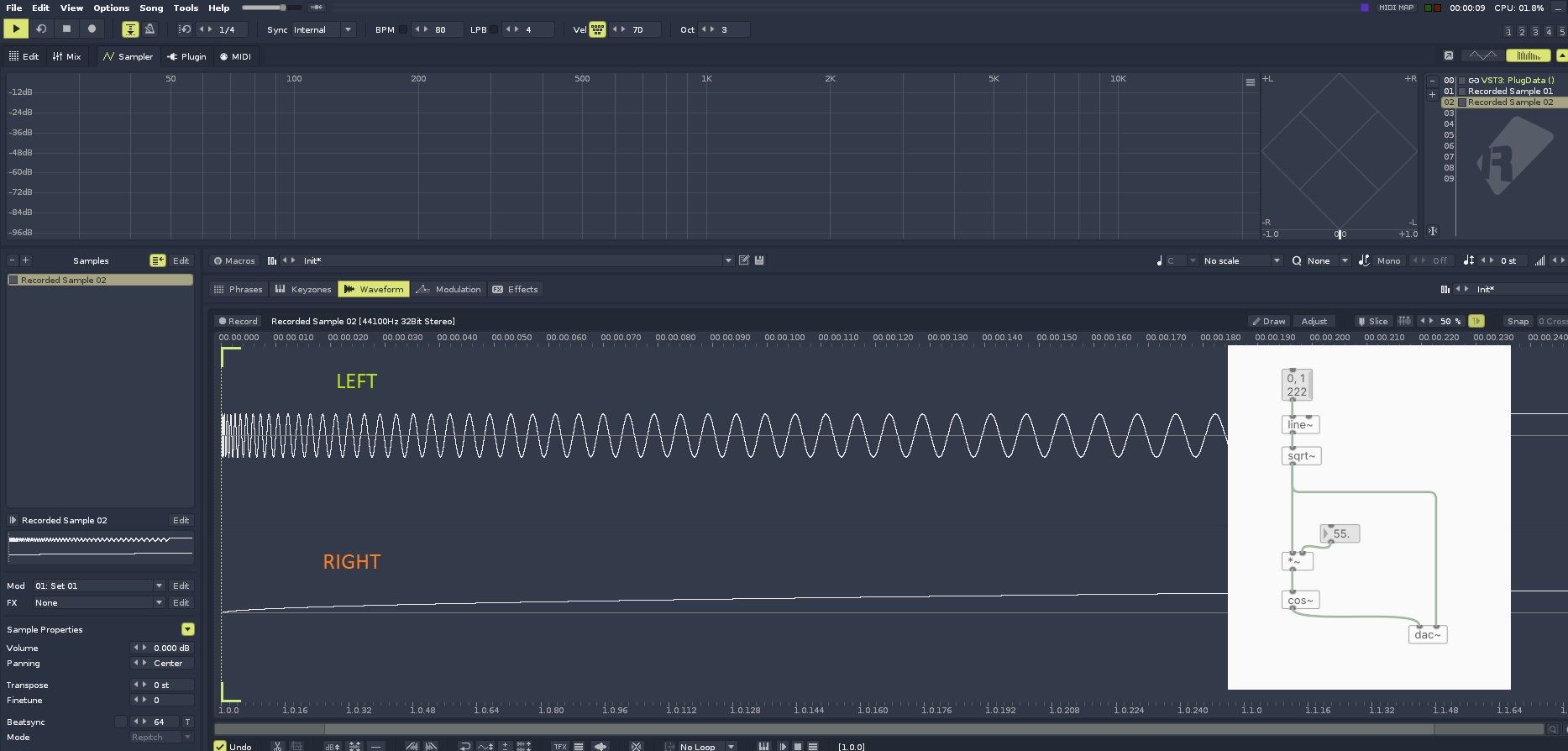
I don't understand why the pitch ( or rather the phase ) of cos~ is falling instead of rising , tbf I really feel like an idiot for not grasping this 
-
Puzzling question about sqrt ~
-
@gentleclockdivider Because the slope of the line determines the frequency, not the value of the line. One would normally drive [cos~] with [phasor~], and if you think about [phasor~]'s output, the lower the frequency, the flatter the slope. Compare with [osc~].
-
I know it determins the frequency( that's w hy I posted the screeshots )
, I am just wandering why the frequency is going from high to low ( pitch bend down ) while the envelope clearly shows it's rising .from 0 to 1 , fast in the beginning = high pitch ° , slower at the end )
DId the same in reaktor ( replaced the line with a ramp wave going from 0 to 1 ) going into a sine function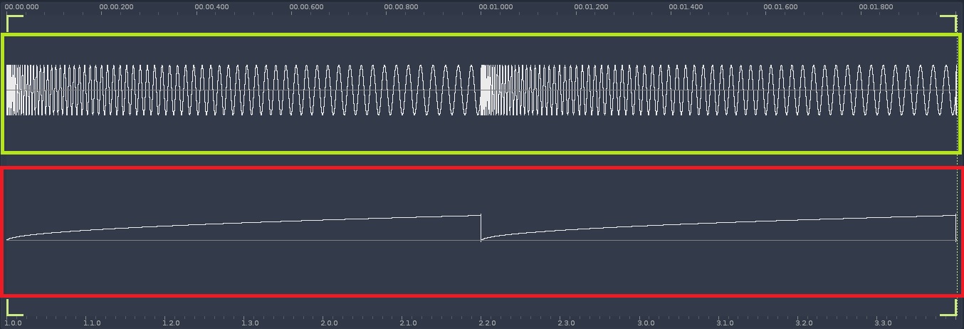
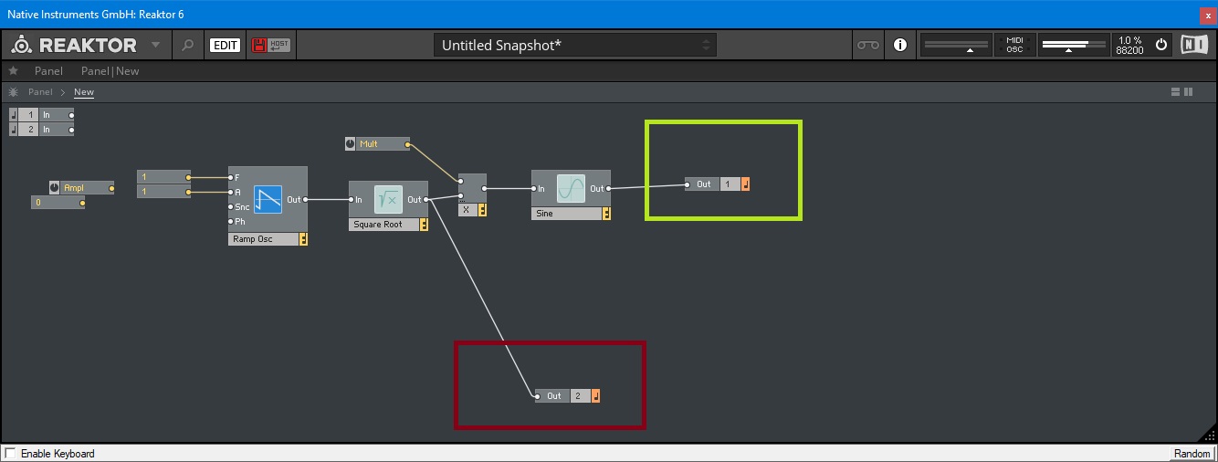
I think I found it but not sure
The envelope going rom 0--1 is rising the pitch because for the sine fuction it doesn' t really matter , iow it runs backwards .
Does that make sense ?
-
Does that make sense ?
no
-
@gentleclockdivider OK, since you know that the slope of the line determines the frequency, the next question to ask is where is the slope the greatest, and where is the slope decreasing. And I suppose to drive the point all the way home, what would you expect if the slope is 0, i.e. the line was flat? And would your answer change if the value of the flat line was 3 vs 3000?
-
Now I'v got it ..( I hope )
The line~ into sqrt does phase distortion
I compared it with ( cyclone ) kink~ (phasor into kink~) which adds a variabe breakpoint to the linear ramp of the phasor
First screenshot shows phasor into sqrt~(upper ) and lower phasor into kink~ .
Second screenshot shows both outputs (left sqrt,right kink ) multiplied and into separate cosines .
The cosine when driven by kink ~ is obviously played a higher pitches before the breakpoint ( steeper rise ) and a steady lower pitch .after that . ( when using mul*)
The sqrt ~ becasue of the conitinous rise has a fallen pitchbend
Always worked with phase disrtion to distort ramps into lookuptables , kind of asurprise its capable of pitchbend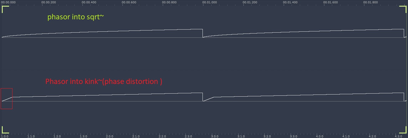

-
@jameslo said:
@gentleclockdivider OK, since you know that the slope of the line determines the frequency, the next question to ask is where is the slope the greatest, and where is the slope decreasing. And I suppose to drive the point all the way home, what would you expect if the slope is 0, i.e. the line was flat? And would your answer change if the value of the flat line was 3 vs 3000?
Asnwer 1 , the slope is the greatest at the beginning , and decreasing shortly after that .
If the slope was 0 and the line flat the cos~ would not be driven .
If the slope was on existent and the line linear we would have a steady cos~pitch -
use the real values, not 0-1 to test things.

