The arduino code is:
#include <FastLED.h>
#define LED_PIN 7
#define LED_PIN2 6
#define LED_PIN3 5
#define LED_PIN4 4
#define LED_PIN5 3
#define NUM_LEDS 1
CRGB leds[NUM_LEDS];
CRGB leds2[NUM_LEDS];
CRGB leds3[NUM_LEDS];
CRGB leds4[NUM_LEDS];
CRGB leds5[NUM_LEDS];
int incoming[5] = {0, 0, 0, 0, 0};
void setup() {
FastLED.addLeds<WS2812, LED_PIN, GRB>(leds, NUM_LEDS);
FastLED.addLeds<WS2812, LED_PIN2, GRB>(leds2, NUM_LEDS);
FastLED.addLeds<WS2812, LED_PIN3, GRB>(leds, NUM_LEDS);
FastLED.addLeds<WS2812, LED_PIN4, GRB>(leds2, NUM_LEDS);
FastLED.addLeds<WS2812, LED_PIN5, GRB>(leds, NUM_LEDS);
Serial.begin(9600);
}
void loop() {
if (Serial.available() > 0) {
// read the incoming byte:
}
incoming [0] = Serial.read();
incoming [1] = Serial.read();
incoming [2] = Serial.read();
incoming [3] = Serial.read();
incoming [4] = Serial.read();
leds[0] = CRGB(incoming [0], incoming [0], incoming [0]);
FastLED.show();
leds2[0] = CRGB(incoming [1], incoming [1], incoming [1]);
FastLED.show();
leds3[0] = CRGB(incoming [2], incoming [2], incoming [2]);
FastLED.show();
leds4[0] = CRGB(incoming [3], incoming [3], incoming [3]);
FastLED.show();
leds5[0] = CRGB(incoming [4], incoming [4], incoming [4]);
FastLED.show();
}```
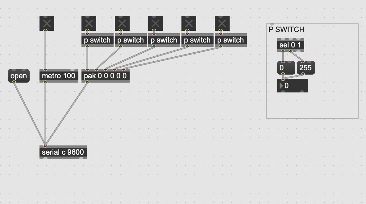
Which works using the following max patch: