Hi,
can somebody please show me a clean and simple example on how to measure elapsed time between two events? Good if it is vanilla compatible too. I am trying to set up a basic gate to filter out fast triggering.
Cheers 
Debouncing (was measure time between two bangs/events)
Hi,
can somebody please show me a clean and simple example on how to measure elapsed time between two events? Good if it is vanilla compatible too. I am trying to set up a basic gate to filter out fast triggering.
Cheers 
@arpPDpi
Yes, that seems like an possible even better solution. I have so far only made a few simple programming tests on the Arduino and in this case I use the Firmata firmware, so I figured trying to add a debounce function to it would be too bold.
But maybe it would not be that complicated?
@cfry Also....... 50cents for 6 buttons....... because...... how long can you bounce my dear switch?
https://hackaday.com/2015/12/09/embed-with-elliot-debounce-your-noisy-buttons-part-i/
David.

@whale-av cool, need to try the hardware solution next round. Great article!
@whale-av said:
@cfry Also....... 50cents for 6 buttons....... because...... how long can you bounce my dear switch?
https://hackaday.com/2015/12/09/embed-with-elliot-debounce-your-noisy-buttons-part-i/
Hi,
I am necromancing this thread a bit. 
I have chosen to debounce in hardware (also, cause I will need to do in Pd too it seems).
I asked about this at the ardunio forum as well, but they suggest (naturally) that I solve it in the arduino code. Since I use the firmata combined with pduino I can not do that.
I would like some help please with choosing the right hardware debouncing configuration. It works pretty ok as of now, but I want to make sure I do not make any errors in selecting electronics. I am debouncing the digital inputs of an arduino nano clone. It seems that I get quite different bouncing on the different inputs.
I am following this guide:
A Guide to Debouncing - Part 2, or, How to Debounce a Contact in Two Easy Pages, by Jack Ganssle
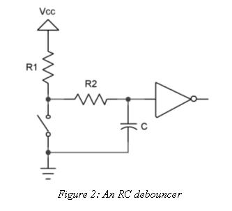
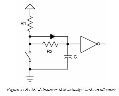
I am choosing between these two configurations:


The math equations are beyond my understanding (I need to get a math textbook sooner or later, to brush up on things).
The latter, with the diode seems to work fine. Suggested values are C: 1 µF, R1: 82K, R2: 18K. I use slightly larger values.
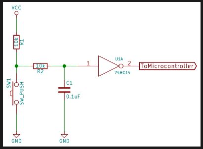
The one without a diode, have example values C: 0.1 µF, R1:? (I used 10K), R2: 185K.
Question
Since I ran out of C 1µF, I used the values from the first circuit, but combined with a diode as in the second circuit. Does this make sense?
Thank you!
@cfry If the diode circuit works well....... and you know the correct values.... then you should source some more 1uf electrolytic capacitors and go with that.
R1 controls the rise time (back to Vcc) and R2 the fall time (to ground).
With the diode the rise time is faster than the fall time as R2 is bypassed.
But there is a handy time calculator for the time to charge the capacitor here...... https://www.digikey.fr/en/resources/conversion-calculators/conversion-calculator-time-constant?
...... so you can see the time with the correct values and work out what resistor value you need if you change the capacitor.
The chip probably has a very high input resistance in which case you can ignore it for your calculations.
None of it makes sense to me because my car squeaks on its own when it hits a pothole, and I will never want an augmented soundscape.
David.
@whale-av Thanks for the explanation and the link. I was using 1uF ceramic ones, why is it better with electrolytic?
And also thanks for the review  I did have second thoughts about showing the project, instead of just talking pd. My intention was not to confuse, actually the opposite. But it makes me curious, what makes sense to you?
@cfry Ha ha, @whale-av was just making a joke about his car. I think it looks really cool, and I'm sure David does too. Glad you posted it.
Having that spring coil hit the top of that machine screw is very steam punk, but my instinct would be to use an IR reflectance sensor. No banging, lasts longer, probably less fun though.
@cfry Sorry, it was just a joke.
The diagram shows electrolytic capacitors. But they are just smaller for the same value..... so as you have the space it doesn't matter. Sorry again to confuse things.
It looks great. I think we are like minded and that is probably true of convinced Pd'ers...... imagining what we can do with what we have available.
David.
Since Pd 0.50 see [slop~] for de-bouncing control data from noisy switches...... [pd jitter-remover] ....... (amongst other uses).
David.
Oops! Looks like something went wrong!