Email
ricky@rickygraham.net
Location
USA
Followers
0
Following
6
Joined
Last Online
-
 ricky
posted in technical issues • read more
ricky
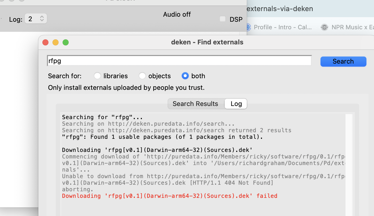
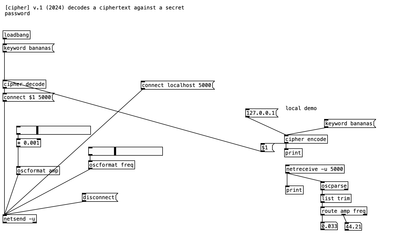
posted in technical issues • read moreHave a look at my granulation external and be sure to let me know if it meets your definition of crap.
https://puredata.info/Members/ricky/software/rfpg/0.1/ -
ricky
posted in this forum • read more
Maybe it's because they're a fictional character from Pokemon?
-
-
-
ricky
posted in technical issues • read more
I pushed an update with intel but it's still showing the older version? How long does it take to catch up or do I need to remove a prior commit somehow?