-
jameslo
posted in patch~ • read more@mosef123 It doesn't (to me), but if you are asking how to generate a stereo sound that draws a square on a GEM oscilloscope when L and R drive X and Y, then here's a way:
square on GEM scope.pd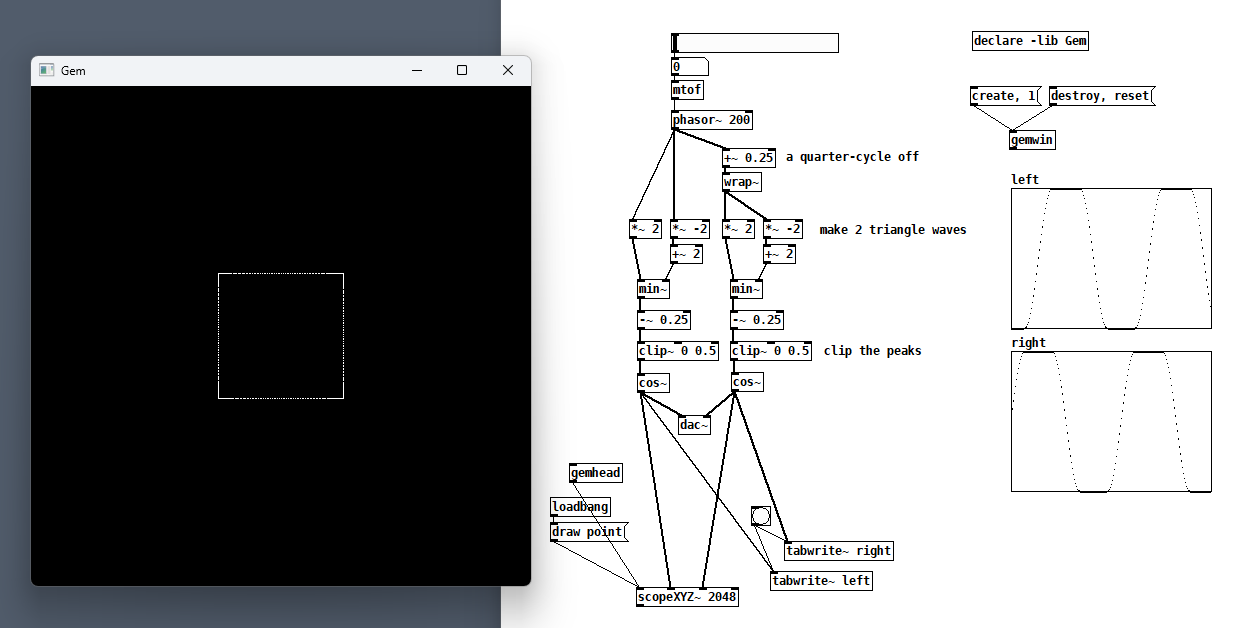
-
posted in technical issues • read more
@hwathwy Well if you have a chance, post what you've tried and why it doesn't meet your requirements. I gotta step out for a few hours but maybe someone else can help you in the meantime.
-
posted in technical issues • read more
@hwathwy Yeah, I'm amazed too, but not with myself, and not in a good way

-
posted in technical issues • read more
@hwathwy Wow, I'd love for someone to explain/defend this behavior because to me it's not good. Why should the behavior of [text get] be different for the same text, dependent on how it was entered? What state is being hidden? Anyhow, I found that the set method for [text define] works more as I would expect, try it and let us know if it works for you.
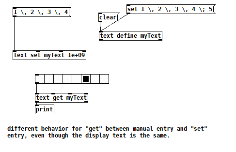
-
posted in technical issues • read more
I figured it out! My last post with a screenshot and instanceIDService3.zip can be made to work with plugdata by replacing [tcpclient] with [netsend -b]. In my previous tests I overlooked that [tcpserver] requires binary mode.
-
posted in technical issues • read more
@jamcultur Oh! I didn't know one could change an application's priority, thanks.
-
posted in technical issues • read more
@ddw_music But couldn't it also be that Pd didn't empty the queue fast enough, either due to Pd being busy doing something else, or Pd not getting enough CPU cycles?
-
posted in technical issues • read more
@ddw_music I tested with multiple Pd processes on Windows and got the same behavior, but my point was: if this is a Pd behavior and there's nothing about running as a plugin that forces one to rewrite the networking facilities, then what can the plugdata team do about it?
-
posted in technical issues • read more
@jamcultur I always turn off all networking when running a show or use a subnet that no one else can access. Maybe note the time when it happens again and then look at the Windows logs to see if anything unusual happened at that time (search "event viewer")
-
posted in technical issues • read more
@jamcultur Do you have MIDI Real-time messages flooding in? Does your patch ever get really busy doing something so that it can't dequeue incoming MIDI events in time? Are you generating bursts of dense MIDI for output? Are there other applications or services running on your computer that steal CPU cycles from Pd? (If you're on a Mac, QLab has a great sheet explaining how to turn off all the things that might interfere with your show)
Maybe try increasing the delay time in audio settings?
-
posted in technical issues • read more
OMG, I'm gonna poke my eyes out. I just updated REAPER from 7.79 to 7.80 and the TCP closing issue changed. The connections still close more slowly than expected, but they at least close now.
-
posted in technical issues • read more
@ddw_music Both--multiple patches in the same Pd instance, or multiple Pd instances on one machine. Not sure why your single process requirement is necessary since some DAWs sandbox plugins. But I'm way out on a limb.
-
posted in technical issues • read more
I'm sad to report that I couldn't get [netsend] to receive responses from [iemnet/tcpserver], I tried all the different ways of responding, including broadcast, so that means this can't be a solution for plugins due to plugdata's limitation on externals. But using [iemnet/tcpclient] totally solves the standalone problem, which was really more of a test case than a problem, and it confirms that it's possible to have private exchanges with clients when there are multiple clients connected to a single port. Additionally, I tested my original [netsend/receive] patches with Audacity+plugdata, and everything worked! So now I think the REAPER problem may be specific to REAPER.
-
posted in technical issues • read more
@ddw_music Why is this a plugdata issue? Does it work in Pd? I'm asking because it would be good to know if plugdata had to rewrite Pd's networking stuff in order to run as a plugin.
-
posted in technical issues • read more
@FFW If there was a way to get your first step to execute reliably (e.g. not dependent upon REAPER's timing), then I would just return an ordinal ID instead of a dynamic port number and my problem would be solved. But yes, if one could solve that first step, then the rest could be a solution to the lack of private connections in [netsend/receive].
I wonder if there's an external that implements a more robust TCP/IP solution, assuming I'm right about [netreceive]'s shortcomings? That would even work with plugdata plugins because the instanceIDService could run in Pd.
Edit: Bingo! iemnet/tcpserver has per client actions. I'll test today and report back.
-
posted in technical issues • read more
I tested with instances running on 2 different machines, and I left the connections open. The "backwards" response to the second instance was also sent to the first instance! So this must be the expected behavior of "backwards", can anyone confirm? i.e. it sends a message back to all connected clients.
I also noticed that [netreceive -f 8000] adds a right-most outlet that lists the originating IP address and port of the incoming connection. It reports the same info as TCPView. If instead of using the "backwards" feature, I try making a netsend connection to the originating IP address and port, the connection is refused. So "backwards" is not the same thing (which is probably obvious to anyone who knows networking).
I see that you can tell the server what port to use for replies if you use UDP, but if the instance could know which ports in a pool of ports were available, then it could derive its own ordinal ID, e.g. if 5 of the ports are already taken, then we must be Number Six (but we would still not know who is Number One).
I added a toggle to show whether [netsend] thinks the connection is open and a numberbox to show how many connections [netreceive] thinks are open, and in the REAPER plugin test, each instance thinks it's open even when nothing is listening on localhost:8000, and there is no error message in any plugdata console. Even weirder, each instance thinks it's closed after the [disconnect( is issued, even though both TCPView and instanceIDService report 6 open connections. Is this a plugdata issue? What other tests would you perform to investigate further? The standalone tests all behave similarly in standalone plugdata.
Finally, I have a theory for why the plugin behavior differs from the standalone behavior. In the latter case, the instances are instantiated so quickly that only the first backward message gets broadcast before all instances disconnect. But REAPER has a lot more work to do, initializing each track, loading plugdata and then restoring plugdata to its saved state, so there's more time between instantiations. The fact that the connections aren't being closed explains why the first instance sees all 6 replies, the second sees the last five, ..., and the last only sees the last reply. So if I make each instance ignore all but the first reply, I get the result I wanted! But in my working life as a programmer, I and my colleagues would've pejoratively called that a hack because it depends on REAPER's timing, which is unspecified, so I'm not really celebrating. For instance, if I run the instanceIDService as the first VST plugin, things are broken.
I'm also going to go out on a limb and say that I think [netreceive] is under-featured. In a Python example I found, they create a socket, bind it to a port, and start it listening. When a client connects, the socket returns a connection from/to which you get/put data. [netreceive] seems to be acting as both the socket as well as the aggregate of all the connections. That's not right! (Or is it?)
test instance ID.zip -
posted in technical issues • read more
@whale-av I think this next test shows that TCP/IP connections are indeed shared when running Pd standalone:
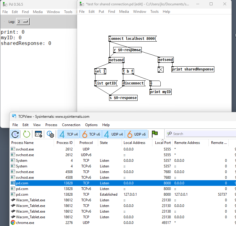
I never requested getID from the right netsend but I got an answer anyway. Note that TCPView shows the right netsend's connection still established as expected. So [netsend/receive] shares data, but not control?Now look at TCPView when I run the REAPER/plugdata VST test and wait a bit:
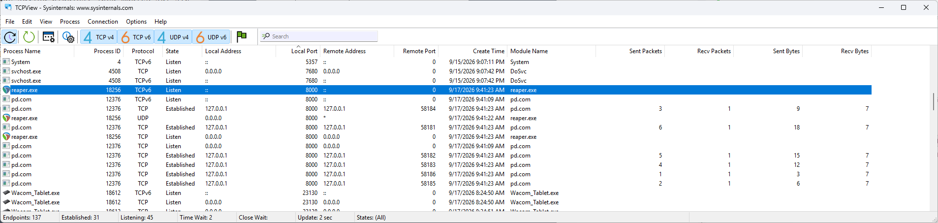
All 6 connections from each of the 6 plugins are still established! What you can't see is that for a while, TCPView was attributing all 6 of those connections to REAPER, but they one by one switched to pd.com. So strange.
But look at the local/remote address and port. See how there's a unique remote port for each established connection? My understanding was/is that these 4 identifiers taken together define the connection, which in this case should be unique, so I shouldn't be getting crosstalk.
-
posted in technical issues • read more
I think my scheme is failing because I'm assuming that several netsends can connect to a single netreceive and have a private connection. That's true over the internet, right? But both the standalone and REAPER behaviors suggest that all instances share the same connection.
-
posted in technical issues • read more
@jyg RE [random], yeah, I thought about that, but my original goal was to know what track I'm on, and I was confident that REAPER loads and initializes each plugin in the same order every time (that appears to be true). A random number would help distinguish the instances (most of the time) but couldn't be used to deduce the track.
-
posted in technical issues • read more
@whale-av "nothing differentiates the instances"--that's the point. If I've used the same plugin on a huge number of tracks but want to modify their behavior slightly per track, there's a lot of configuring to do. If I have to make each instance go to a different port, then that's the same amount of manual work as the configuration I'm trying to avoid. I'm trying to make something like the clone ID $1.
This morning I'm remembering that my code works the first time, as I am adding tracks or plugin instances one at a time, so maybe I just have to save that ID and disable getID for subsequent runs, i.e. when REAPER reloads the project, I dunno.