@oid said:
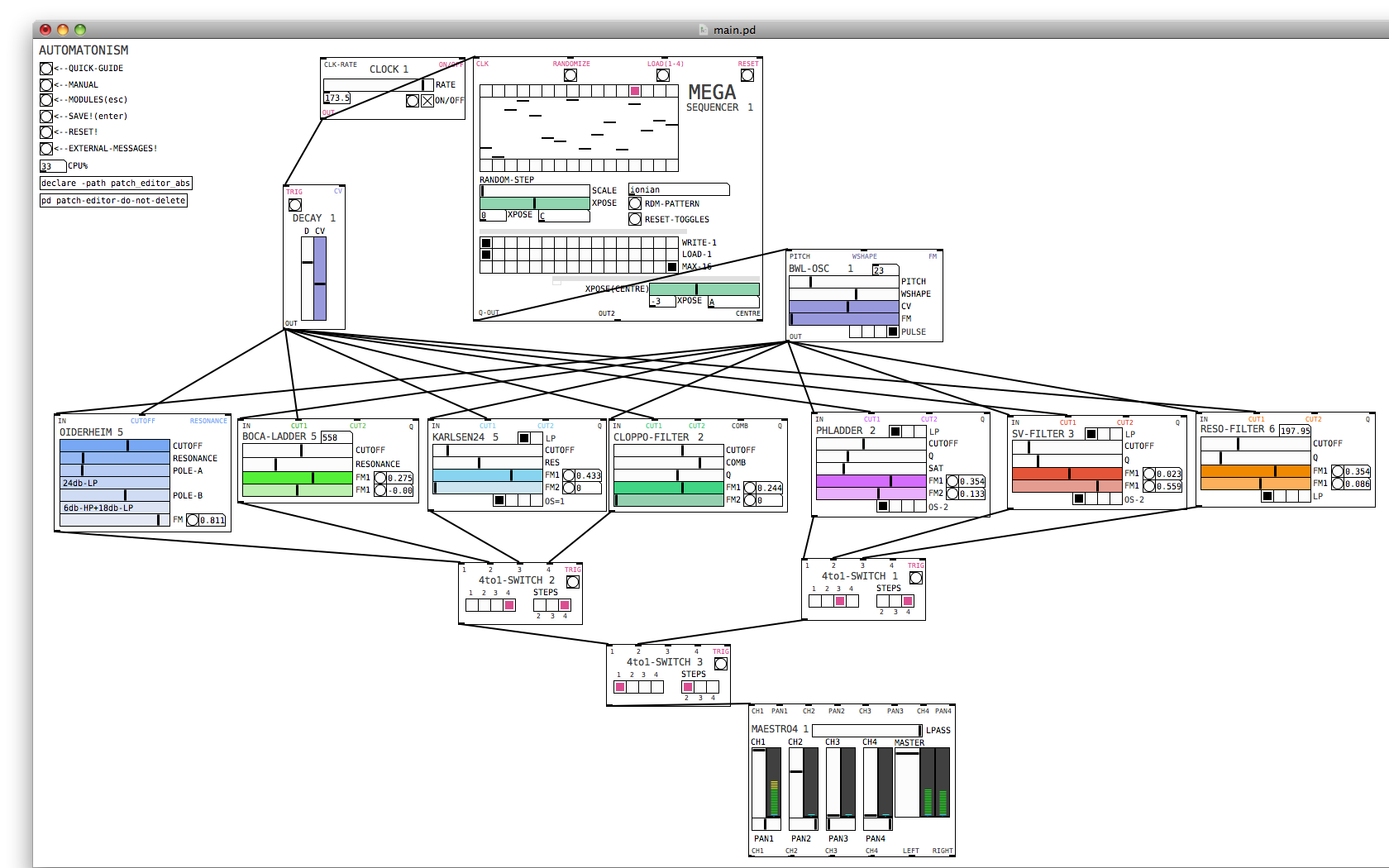
I am referring to it being made up from multiple objects instead of just one, analogy between transistors and integrated circuits.
Ok well, I was refering to the inherent phase shift that any digital filter has because of the discrete time and delay. No biggie.
Probably not control vs signal domain since they both have [mtof] on the cutoff so should be set to the exact same frequency. I am not talking about cancellation during the morph, as I said some transitions don't work, a resonance morph from 24db hp to 12db lp works but 24db hp to 18db lp results in the resonance results in the wrong phase after the morph, but a morph from 12db lp to 18db lp works just fine (don't recall if those actual transitions are the troublesome ones, just a random example). I suspect an error that can only be seen on the text level, order of operations (don't see anywhere this could be the issue) or an actual error which can not be seen in the patcher like the duplicate patch cable bug. I am fairly certain this just recently cropped up and the non-[lop~] filters did work but that might have just been an illusion caused by the mysterious 10 sample delay which had cropped up some how, I have no idea, hence starting over from scratch come weekend.
For resonance to work, there has to be a full 360 degree shift of the cut-off frequency while the other frequencies get cancelled/phased out. This works when you have 4 1 pole filters doing 45 degrees shift on the cutoff frequency each and then do negative (180 degree shift) feedback. But when you start mixing the different poles for the feedback you get all sorts of different phase distortions that wont create the magic self oscillation we love so much. Maybe try using the [filter-graph] abstractions from H10.measurement.pd to measure phase distortion on your resonance pole-mix and see what is going on.
As an aside, know of any suitable externals which is essentially [lop~] with signal rate? I looked some but only found more complex filters, would be nice to have that CPU savings which [lop~] provides but keep signal rate inputs. Or is the CPU difference primarily the signal rate cutoff? Seems too great to be just that.
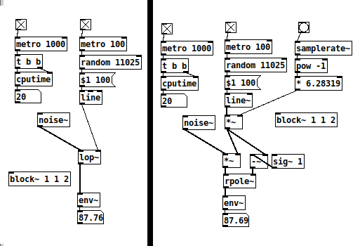
I just ran a test on [rpole~] vs [lop~] (seppareately!)

Setting [rpole~] up like here, it works 'exactly* like [lop~]. They both spike at 30 CPU but stay at 20 most of the time. I think [rpole~] is as cheap as it gets with signal rate cut-off control. Of course, small differences add up when you have several instances.


